
Pacific Pro Group portfolio
Split-level duplex conversion
Explore the house layer by layer: the finished house, the street side, the roofs, the first floor, the ground floor and the basement.
Choose a layer, or select Explore to turn the model and go to a room.
Select Explore to turn and zoom the model. Arrow keys turn. Shift with arrow keys pans. Plus and minus zoom. Zero resets. Escape ends exploring. Use Go to a room for a close view.
How to explore
Mouse or touch. Select Explore, then drag to turn. Use the zoom buttons, scroll or pinch to zoom. Right-drag or use two fingers to pan. Choose a room from the menu, or select a room in the drawing, to move closer. Choose Done exploring to scroll the page again.
Keyboard. Focus the drawing and press Enter. Arrow keys turn; Shift with arrow keys pans. Plus and minus zoom, 0 resets, and Escape ends exploring. Use the layer buttons or slider to reveal the house.
Top view looks straight down at the plan. Zooming in lifts the roof and reveals room names. Reset view returns to the selected layer.
- Master Bedroom
- Living Room
A split-level duplex: a two-story block with a basement under a first floor unit, and a one-story ground floor wing half a level between them. Choose Explore to turn the model or go to a room.
How the model was made
Modeled from the architect's existing and demolition floor plans for all three levels at 3/16 inch = 1 foot, the site plan and the owner's marked-up conversion sketches. Walls, openings, stairs, room names and the printed room sizes come from those sheets. The set has no elevations, sections or roof plan, so every height and the roof are assumptions, listed below.
Roof. The site plan draws the roof outline: an east-west gable over the two-story block and a north-south gable over the ground floor wing that ends in a Dutch gable, a hip below a small gable, at the street. No pitch or height is printed; at an assumed 5:12 pitch the two roofs meet where the site plan shows.
Openings. Window and door widths are traced from the floor plans. The set has no elevations, so window and door heights are assumed. The two entries to unit 1 follow the owner's sketch, one on each side of the ground floor.
Room layout. Room names and sizes are shown as printed on the plans. Each of the two inside stairs is drawn with six treads, so each climbs half a level: from the basement up to the ground floor, and from the ground floor up to the first floor. At an assumed 7 1/2 inch riser the ground floor sits 4'-4 1/2" above the basement and the first floor 8'-9". The first floor kitchen, dining area and living room are one open space; the lines between them follow the printed room sizes.
- Three levels, half a level apart
- Two units today
- Four bedrooms, two baths
Modeled from the architect's existing and demolition floor plans for all three levels at 3/16 inch = 1 foot, the site plan and the owner's marked-up conversion sketches. Walls, openings, stairs, room names and the printed room sizes come from those sheets. The set has no elevations, sections or roof plan, so every height and the roof are assumptions, listed below.
Assumptions (not printed on the plans)
- Walls are read from the architect's vector floor plans at 3/16 inch = 1 foot and checked against the printed dimension strings: the two-story block is 30'-0" by 24'-11" and the ground floor wing 23'-0" by about 19'-4".
- No heights are printed. Each inside stair is drawn with six treads (seven risers); at 7 1/2 inch risers the ground floor sits 4'-4 1/2" and the first floor 8'-9" above the basement floor. Ceilings on the ground and first floors are assumed 8'-0".
- Windows are traced from the plans; their heights are assumed: sills 3'-0" and heads 6'-10" above each floor, with basement sills 4'-0" above the floor to clear the ground.
- The ground is assumed level, 3'-0" above the basement floor and 1'-4 1/2" below the ground floor, from the outside stair drawn on the north side. The site plan contours fall a few feet toward the street; that slope is not modeled.
- The roof follows the outline on the site plan with 18 inch overhangs. The pitch is assumed 5:12, which brings the two ridges to meet within a foot of where the site plan draws it.
- The two basement options on the sheets are crossed out, so the basement is shown as it stands, including the walls the demolition plan marks in red. The ground floor and first floor follow the owner's conversion sketch: an entry to unit 1 on each side of the ground floor and the stair between the ground and first floors opened up.
- A few printed room areas do not match their printed sizes (the breakfast nook, the master bedroom and the basement bedrooms); room labels show the sheet's values as printed.
- The outside stair to the first floor door is drawn on the plans; the stair down to the basement door beside it is cut off at the sheet edge, so its well and steps are assumed. An angled stair shown with a break line under the first floor at the east landing is not modeled because the sheets do not show where it goes.
- Interior doors are shown as open gaps. Kitchen and bath fixtures, closet shelving, siding and trim are not modeled.
Board feature
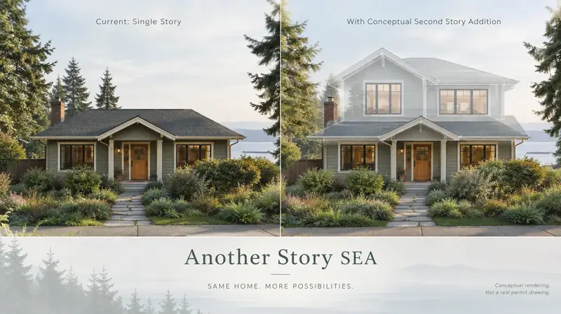
Another Story
Same home. Another story. Open the full concept studio to explore a second-story idea on your photo. Concept preview only, not a bid or permit document.