
Pacific Pro Group portfolio
Hillside post-and-beam house with a lower-level ADU
Explore the preliminary design layer by layer: the house on its slope, the entry side, the flat and planted roofs, the upper floor, the main floor and the lower-level ADU.
Choose a layer, or select Explore to turn the model and go to a room.
Select Explore to turn and zoom the model. Arrow keys turn. Shift with arrow keys pans. Plus and minus zoom. Zero resets. Escape ends exploring. Use Go to a room for a close view.
How to explore
Mouse or touch. Select Explore, then drag to turn. Use the zoom buttons, scroll or pinch to zoom. Right-drag or use two fingers to pan. Choose a room from the menu, or select a room in the drawing, to move closer. Choose Done exploring to scroll the page again.
Keyboard. Focus the drawing and press Enter. Arrow keys turn; Shift with arrow keys pans. Plus and minus zoom, 0 resets, and Escape ends exploring. Use the layer buttons or slider to reveal the house.
Top view looks straight down at the plan. Zooming in lifts the roof and reveals room names. Reset view returns to the selected layer.
- Flexible Living Room
- Bedroom 1
- Bedroom 2
- Unfinished Storage
- Patio
- Kitchen
- Dining
- Living Room
- Garage
- Foyer
- Office / Guest Suite
- Bath
- Deck
The house on its hillside: a post-and-beam main floor with a planted roof, an upper floor box above it and a daylight lower level that opens to the back. Choose Explore to turn the model or go to a room.
How the model was made
Preliminary design, modeled from the design drawings: the main, upper and lower level plans at 1/8 inch = 1 foot, four elevations and the 3D plan views. Walls, wall openings, room names, the level areas, the floor to floor heights and the roof outline come from those sheets. The design may still change. Anything the sheets do not print is listed below as an assumption.
Roof. From the elevations and the 3D views: two flat, low roofs with deep overhangs, one over the main floor and one over the upper floor. The main roof outline is drawn on the upper level plan, where it is labeled green roof. The back elevation prints three 10'-6" steps, so the main roof sits 10'-6" above the main floor and the upper roof 10'-6" above the upper floor.
Openings. Window and door widths are the gaps in the exterior walls on the plans, mostly 4'-11" bays between the posts of the 5'-6" building grid. The plans print no window schedule, so sills and heads are scaled from the elevations by window type: tall glass to the back, high transom windows on the street sides.
Room layout. The plans print the area of each level but no room areas, so rooms show their names only. Select a room to fly in.
- Preliminary design
- 3,587 SF on three levels
- 1,179 SF lower-level ADU
Preliminary design, modeled from the design drawings: the main, upper and lower level plans at 1/8 inch = 1 foot, four elevations and the 3D plan views. Walls, wall openings, room names, the level areas, the floor to floor heights and the roof outline come from those sheets. The design may still change. Anything the sheets do not print is listed below as an assumption.
Assumptions (not printed on the plans)
- This is a preliminary design. The drawings say the design may change.
- Walls are traced from the plan drawings at 1/8 inch = 1 foot, checked against the printed 5'-6" building grid. No overall dimensions are printed.
- Floor to floor heights are the printed 10'-6" steps on the back elevation. Walls stop 1'-0" below the next level for the roof and floor edge; that depth is scaled from the elevations.
- Window and door heights are scaled from the elevations by window type. There is no window or door schedule.
- The main roof outline is the line drawn on the upper level plan. The upper roof overhang, about 2'-0", is scaled from the elevations. Both roofs are drawn flat; their slope for drainage is not printed.
- The green roof is drawn over the whole main roof outside the upper floor, as the upper level plan labels it. Planting and parapet details are not shown.
- The ground is drawn as simple planes scaled from the side elevations: level with the lower floor behind the house, rising to the main floor on the street side, and stepping down beside the walk stair to the lower level entry. The lot shape, the full 16 foot fall across the lot and any retaining walls are not modeled.
- The stairs are drawn as straight flights of 17 risers, scaled from the plans. The riser count is not printed.
- The walk steps between the lower entry and the main level walk are the nine treads drawn on the plans; their rise is assumed even.
- Two rooms with no printed name are labeled Bath (unlabeled) from their plumbing fixtures.
- The two deck columns are the outlined 2'-0" x 6" rectangles on the deck edges of the main level plan. The deck guard follows the back and side elevations: horizontal metal bars with a dark top rail, about 3'-0" above the deck (scaled), with a wood rim band under the deck edge.
- The north walk stair to the lower level entry is drawn as on the plans. No retaining wall is drawn on the plans, so none is modeled.
- Furniture and fixtures sit where the plan symbols are, scaled from the drawing. Their heights are assumed. Interior doors are shown as open gaps, except the upper laundry bi-fold doors and the bonus room closet doors, drawn open as the plan shows them.
- Beam ends under the overhangs are the dashed beam lines on the plans where they run past the walls. Their 1'-0" depth is scaled from the back elevation.
- Siding, cedar trim and soffits, posts and beams inside the glass walls, and window mullions are not modeled. The entry door is shown in warm wood, as on the front elevation.
Board feature
Another Story
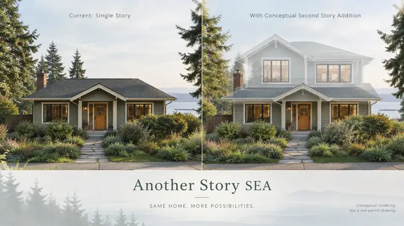
Same home. Another story. Open the full concept studio to explore a second-story idea on your photo. Concept preview only, not a bid or permit document.